Heat shield - Sense or Nonsense?

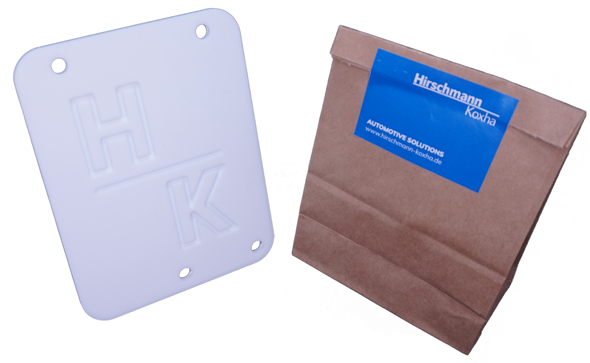
Lately, we have noticed that more and more customers prefer relocating the control unit over our protective plate. But is this really so sensible? Sense or Nonsense? An Examination.
The problem
But let's begin with the initial situation. The protective plates are designed for the Trionic 8 control units, which are positioned directly on the intake manifold, thus in close proximity to the engine block. Anyone who has touched the hood after a long drive is aware of the heat radiating from the engine block. Depending on the engine type and the positioning of various components (especially the turbocharger and exhaust manifold), temperatures can reach up to 100°C - almost like a small oven.
Thermal cycles
After analyzing the initial situation, it is important to clarify to what extent these temperatures can damage electronic components. After all, solder only becomes liquid at temperatures around 200°C, and many components are resilient beyond these temperatures. The real issue, therefore, does not solely lie in the temperature itself.
Thermal cycles are a significant concept in material science and electronics engineering. They refer to repeated fluctuations in temperature to which a material or component is exposed. Over time, these temperature variations can lead to mechanical stresses and potential damage to the material. Thermal cycles are a common issue in many applications, especially in electronics and the automotive industry, where components repeatedly expand and contract due to heating and cooling.
The effects can be as follows:
- Material Fatigue: Repeated expansion and contraction can lead to the formation of cracks and stresses in materials, which can result in material fatigue over time.
- Solder Joints: In the electronics industry, thermal cycles can cause solder joints on assemblies to break, leading to malfunctions or failures.
- Deterioration of Electrical Properties: The electrical properties of components and circuits can change with repeated temperature cycles, affecting their performance.
- Deformation: Mechanical components can deform due to thermal expansion and contraction, leading to inaccuracies or functional issues.
To illustrate this with a practical example, consider the following scenario: You start your vehicle in the morning and head to work. Initially, the engine is cold. However, as you drive for some time and come to a stop at a traffic light, heat accumulates because there is insufficient airflow to provide cooling.
Your control unit is also affected by this. The most vulnerable area is the underside of the control unit, which is directed towards the intake manifold. Due to its aluminum casing, it has a relatively high coefficient and heats up quickly. Internally, the components and solder joints start working due to thermal expansion.
When you start driving again, the airflow through the engine compartment cools the components once more. Depending on your driving route, this process can repeat multiple times.
The solution
A good protective plate addresses this very point. The goal is not to completely dissipate the heat, but to cushion the expansion and cooling processes. Our protective plates have one of the lowest thermal coefficients available. This means that both heating up and cooling down occur very slowly, making them ideal for routes with frequent stop-and-go operation.
Aluminum versions, on the other hand, take the opposite approach. They serve more as 'reflectors' and lack such thermal buffering capabilities, making them better suited for highway and rural road driving.
A Note of Caution From Us
At this juncture, we would like to draw our customers' attention to seemingly 'attractive' protective plates being marketed in the USA or Poland. Our investigations have revealed that the materials used in these products do not meet the technical requirements and may, at times, pose a risk to the operational safety of vehicles. Please ensure that the protective plates you choose are made from materials approved for technical applications.
Our protective plates are manufactured from food-grade PTFE, which we can readily verify through the appropriate certificates.
Sources
Musallam, M., & Johnson, C. M. (2010). Real-time compact thermal models for health management of power electronics. IEEE Transactions on Power Electronics, 25(6), 1416-1425.
Pang, J. H., Chong, D. Y. R., & Low, T. H. (2001). Thermal cycling analysis of flip-chip solder joint reliability. IEEE Transactions on components and packaging technologies, 24(4), 705-712.
Jiao, Y., Jermsittiparsert, K., Krasnopevtsev, A. Y., Yousif, Q. A., & Salmani, M. (2019). Interaction of thermal cycling and electric current on reliability of solder joints in different solder balls. Materials Research Express, 6(10), 106302.
Vasudevan, V., & Fan, X. (2008, May). An acceleration model for lead-free (SAC) solder joint reliability under thermal cycling. In 2008 58th Electronic components and technology conference (pp. 139-145). IEEE.

Disclaimer
While our article does not claim to provide a scientific contribution or information of scientific quality, we nevertheless provide references to allow readers the opportunity to independently verify the presented facts.


